More than just a threaded aluminium tube, our 600 mm adjustable leg, an essential component of our scaffold towers, is a testament to precision engineering.
Several workers can use the equipment simultaneously at different levels, as it is designed to support loads of up to 275kg per trap door platform level, up to a maximum of 950kg per industrial scaffold tower, while adapting to uneven terrain.
LEWIS Access’s manufacturing process is a carefully orchestrated dance of material science, machining, and rigorous quality control.
This article explains how we manufacture our 600 mm adjustable legs.
Table of Contents
Step-by-Step Manufacturing Process of 600 mm Adjustable Legs
Step 1: Delivery of Raw Material
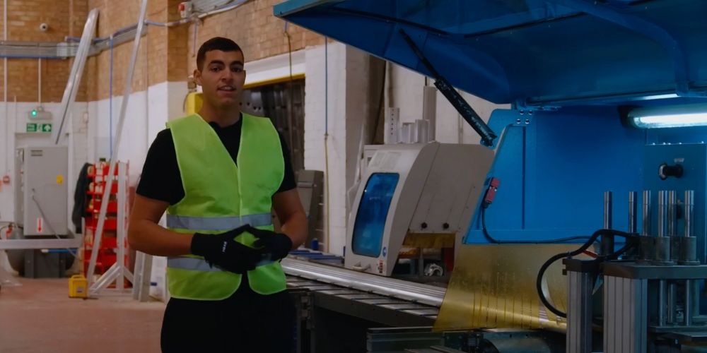
Our supplier sends us aluminium tubes, which arrive in our factory in standard lengths of 6,005 mm. It’s then placed onto the machine’s bed when required.
Step 2: Programming the Cutting Parameters
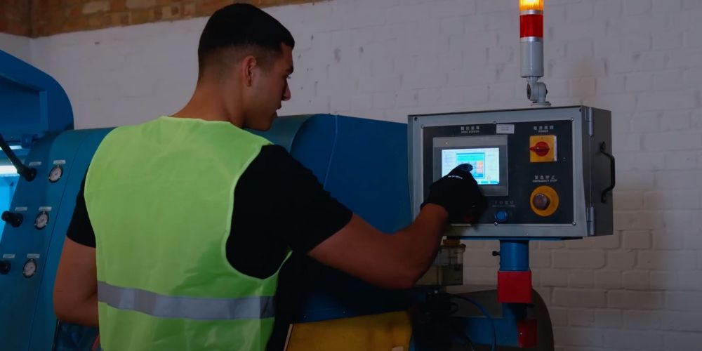
Next, we program the machine with the exact dimensions required for our adjustable legs. This involves inputting two key measurements:
- Initial material length: we inform the machine that the starting length of the raw material is 6,005 mm.
- Desired cut length: we specify that we need each leg to be 598 mm long.
Step 3: Calculating and Initiating the Cuts
With these inputs, the machine calculates how many pieces of the desired length can be efficiently cut from the initial raw material. In this case, our calculations allow us to output nine exact cuts of our adjustable legs from each 6,005 mm piece.
Step 4: Utilising the Trim Stopper for Accuracy
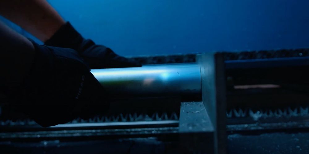
We push the raw material firmly against the trim stopper to ensure absolute precision and eliminate any tolerance issues. This is the machine’s zero point, providing a consistent starting reference for every cut.
Step 5: Securing the Material
Once the raw material is positioned against the trim stopper, we securely clamp the tubes in place. This prevents any movement during the cutting process, guaranteeing the accuracy of each individual cut.
Step 6: The Initial Trim Cut
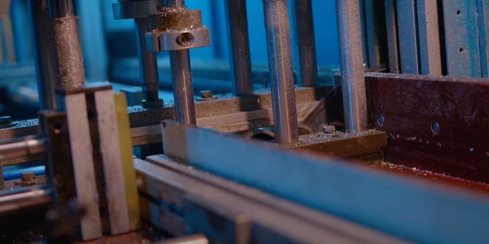
The first action of the saw is a small but vital trim. It cuts 4 mm off the very top of the raw material. This initial cut ensures a clean and perfectly square starting edge for the subsequent precise cuts.
Step 7: Making the Precision Cuts
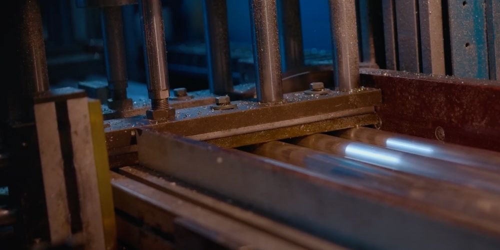
With the initial trim complete, the machine now executes the primary cuts. The saw precisely cuts the material at exactly 598 mm intervals.
Step 8: Quality Control – The First Cut Verification
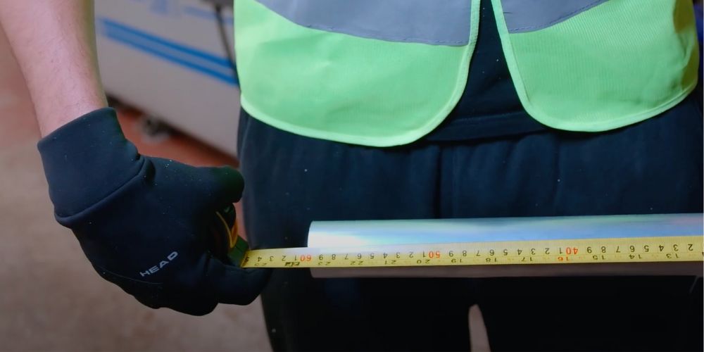
The first piece that has been cut now enters our quality control “safe zone.” Here, we meticulously measure this initial cut with a tape measure. Our expectation is that it will measure 598 mm.
Step 9: Confirmation of Precision
And the result? Brilliant! The first cut meets our exact specifications, confirming the accuracy of the machine setup and our process. This successful first cut assures us that the subsequent eight cuts will also meet our high standards for our adjustable legs, and it’s ready to proceed to the next stage.
With our tubes now precisely cut to the required 598 mm length, the journey towards becoming fully functional adjustable legs continues in another specialised area of our factory. Here, the cut tubes are transferred to a Computer Numerical Control (CNC) machine for further refinement.
Step 10: Transfer to the CNC Machining Area
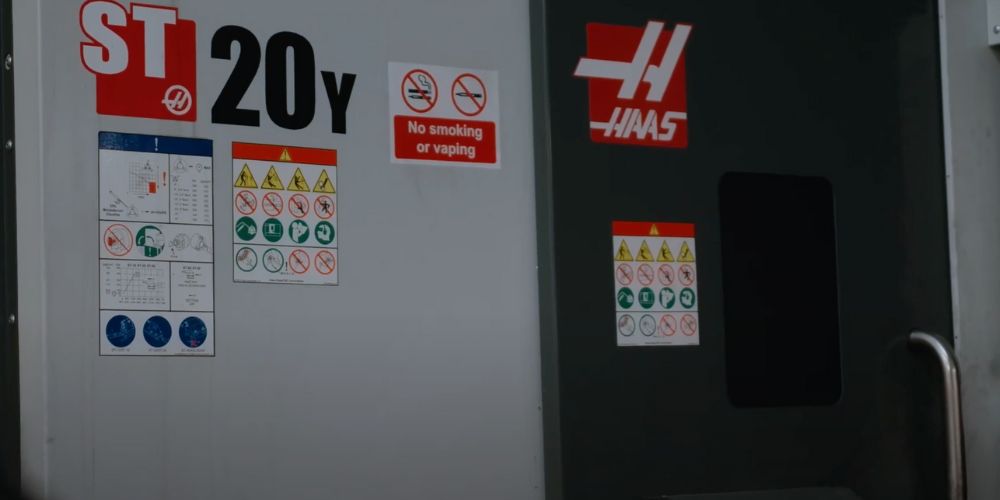
The accurately cut tubes are carefully transported to the section of our factory housing our CNC machinery – the state-of-the-art ST20y. This advanced piece of equipment is instrumental in transforming the simple cut tubes into the final, functional adjustable legs.
Step 12: Increasing the Internal Diameter
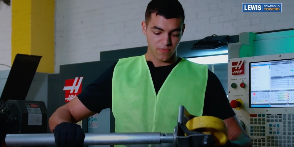
The initial task for the CNC machine is to increase the internal diameter of the tube. This crucial step is necessary to ensure that the castors (wheels) will fit comfortably and securely inside the leg.
Step 13: Securing the Tube in the Chuck
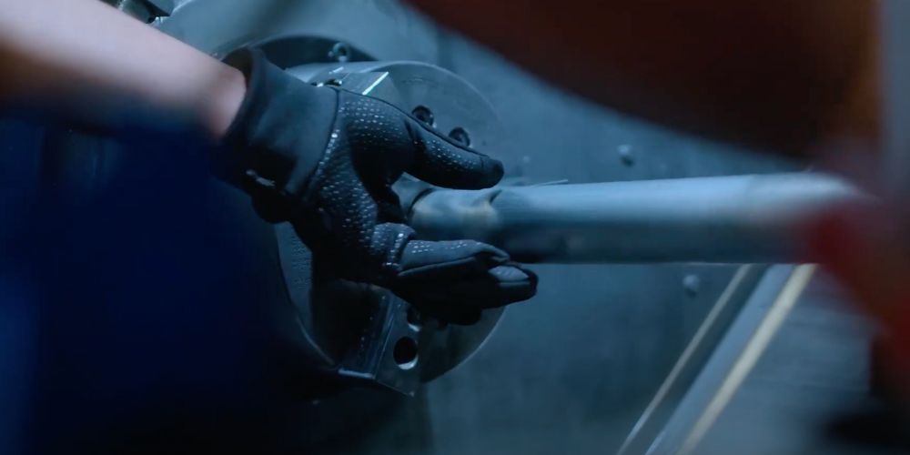
To begin the machining process, each tube is placed into the chuck. This is a specialised clamping mechanism designed to securely hold cylindrical workpieces like our tubes, ensuring stability during the precise operations. Similar to where you place a drill bit in a drill.
Step 14: Establishing the Machine’s Zero Point,
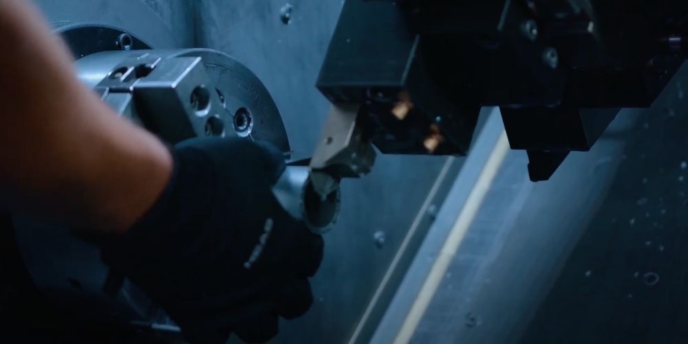
Similar to the cutting stage, we establish the zero point for the CNC machine. The tube is carefully positioned against this reference point on the machine, providing a consistent starting position for all subsequent operations.
Step 15: Incremental Drilling for the Perfect Fit
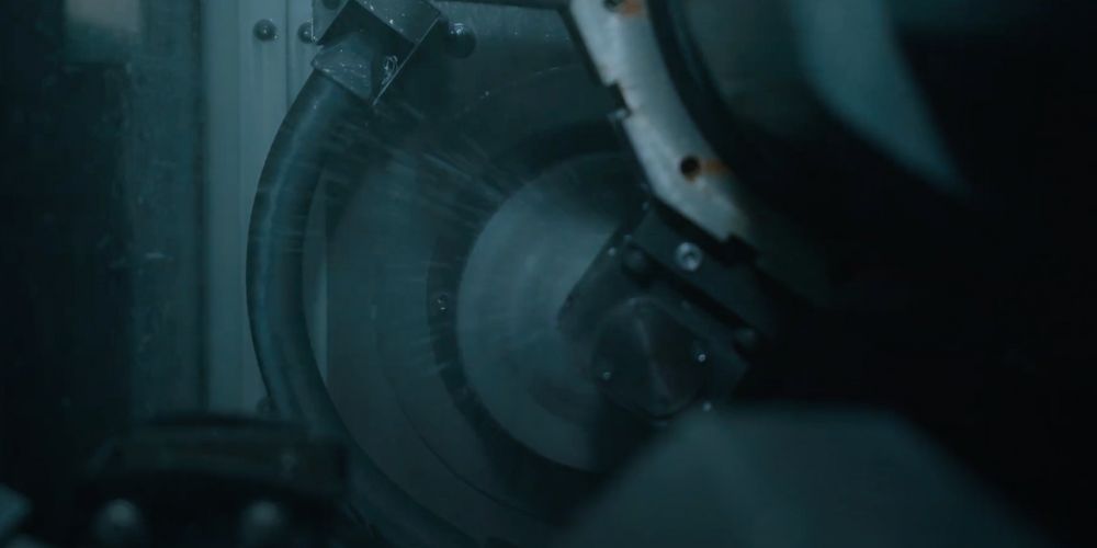
The CNC machine then begins the process of increasing the internal diameter. This is achieved by drilling millimetre by millimetre. This gradual approach ensures accuracy and prevents any damage to the tube as the internal space is carefully enlarged to the precise dimensions required for a comfortable and secure castor fit.
With the internal diameter now correctly sized, the adjustable legs are one step closer to completion, ready for the next stage of the manufacturing process on the CNC machine. The next critical step on the CNC machine is creating an internal thread. This thread will be essential for securely attaching other components to our adjustable legs.
Step 16: Positioning Against the Threading Zero-Point
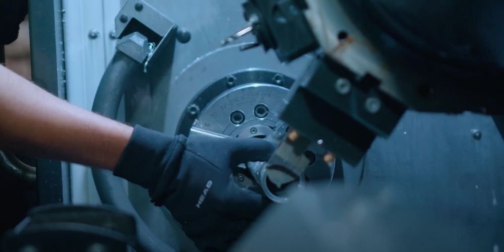
To prepare for threading, we carefully push the tube up against another designated zero point on the CNC machine. This new reference point ensures that the internal thread will be created in the precise location required along the length of the tube.
Step 17: Incremental Thread Creation
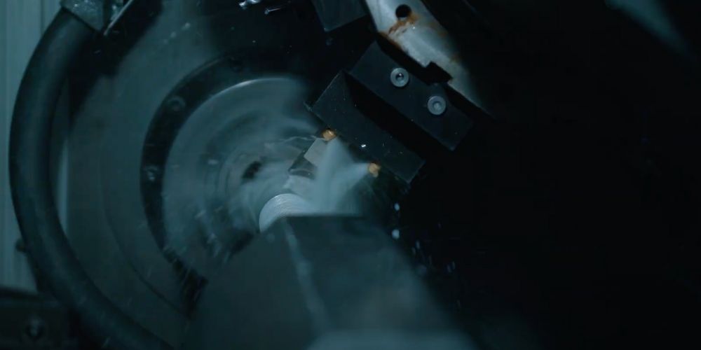
The CNC machine now begins the delicate process of creating the internal thread. Working a millimetre at a time, the machine carefully cuts the helical groove into the inner surface of the tube.
Step 18: Multiple Passes for Accuracy and Protection
To achieve a high level of accuracy and prevent any potential damage to the newly forming thread or the machine itself, the CNC machine goes over the thread multiple times. This iterative process ensures a clean, consistent, and robust thread that will function reliably in the final product.
Step 19: Cooling and Clearing Debris
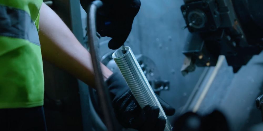
Once the threading process is complete, it’s essential to remove any swarf or shavings (small pieces of material produced during machining). We do this by spraying off the sheds with a coolant. This not only clears the debris but also helps to cool the newly threaded area.
With the internal thread now precisely formed and cleared, the adjustable legs are taking their final shape, ready for the subsequent stages of assembly. The final stage on the CNC machine focuses on creating a crucial safety feature and ensuring the impeccable quality of our adjustable legs.
Step 20: Creating the Pin Locking Incisions
To prevent the adjustable leg from accidentally detaching from our scaffold tower products, the CNC machine now performs two distinct incisions:
1. Lined incision (one side): a continuous, linear cut is made on one side of the tube.
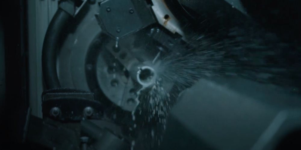
2. Dotted incision (opposite side): a single hole is cut on the opposite side.
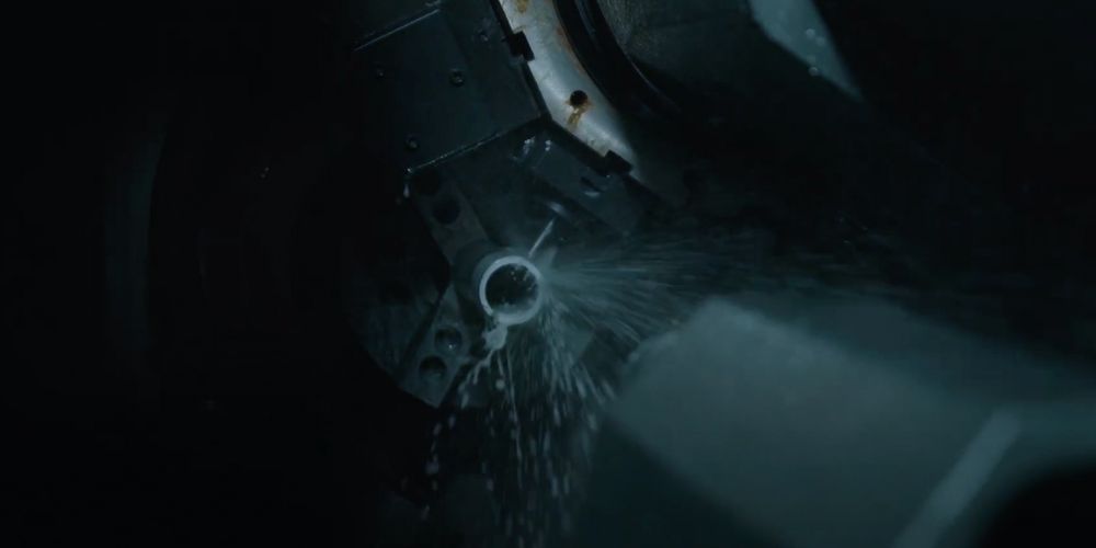
These specific incisions are designed to work in conjunction with a pin. When the pin is inserted through these incisions, it creates horizontal pressure inside the adjustable leg. This pressure acts as a secure locking mechanism, effectively stopping the leg from falling out of the scaffold tower during use.
Step 21: Smoothing the Edge for Precision
Before making these critical incisions, the CNC machine is allowed to move to its zero point. It then carefully moves (“saunters”) over the edge of the tube to create a smoother surface. This meticulous step highlights the incredible accuracy of the machine and ensures that the subsequent incisions are clean and precisely placed. In our pursuit of zero error, this level of detail is paramount, guaranteeing a near-perfect product every time.
Step 22: Final Quality Control Checks
With the safety incisions complete, the final stage involves rigorous quality control to ensure every adjustable leg meets our exacting standards:
1. Thread verification: we take a corresponding nut and attempt to thread it onto the newly created internal thread. A smooth and secure fit confirms the accuracy and integrity of the threading process.
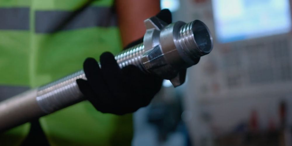
2. Pin insertion test: finally, we insert the intended safety pin into the lined and dotted incisions. A proper fit and the creation of the intended horizontal pressure confirm the functionality of this crucial safety mechanism.
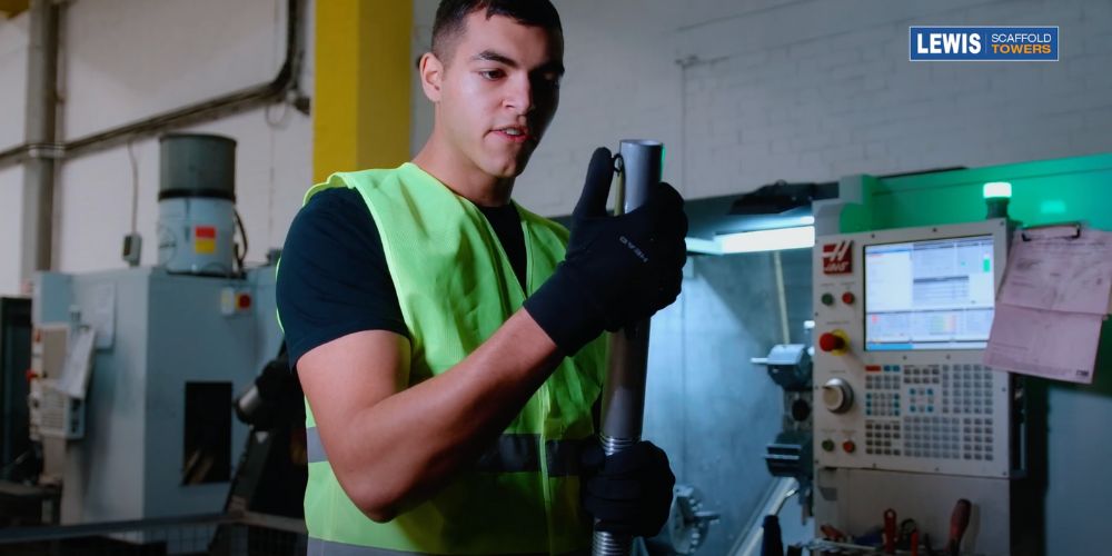
This final quality control step assures us that each adjustable leg leaving our CNC machine is not only precisely manufactured but also incorporates the essential safety features required for reliable and secure use in our scaffold tower products.
Wrapping It Up
This meticulous attention to detail throughout the entire process defines the quality, dependability, and safety of our adjustable legs. All components are supplied when you buy our scaffold towers, and you can easily buy spare 600mm adjustable legs if required.

